 Youtube
Lets see how does it working:
What is Press-fit?
Press-fit is an interference fit between two parts in which one part is forced under pressure into a slightly smaller hole in the other.
Literally, it is a kind of interference fit.
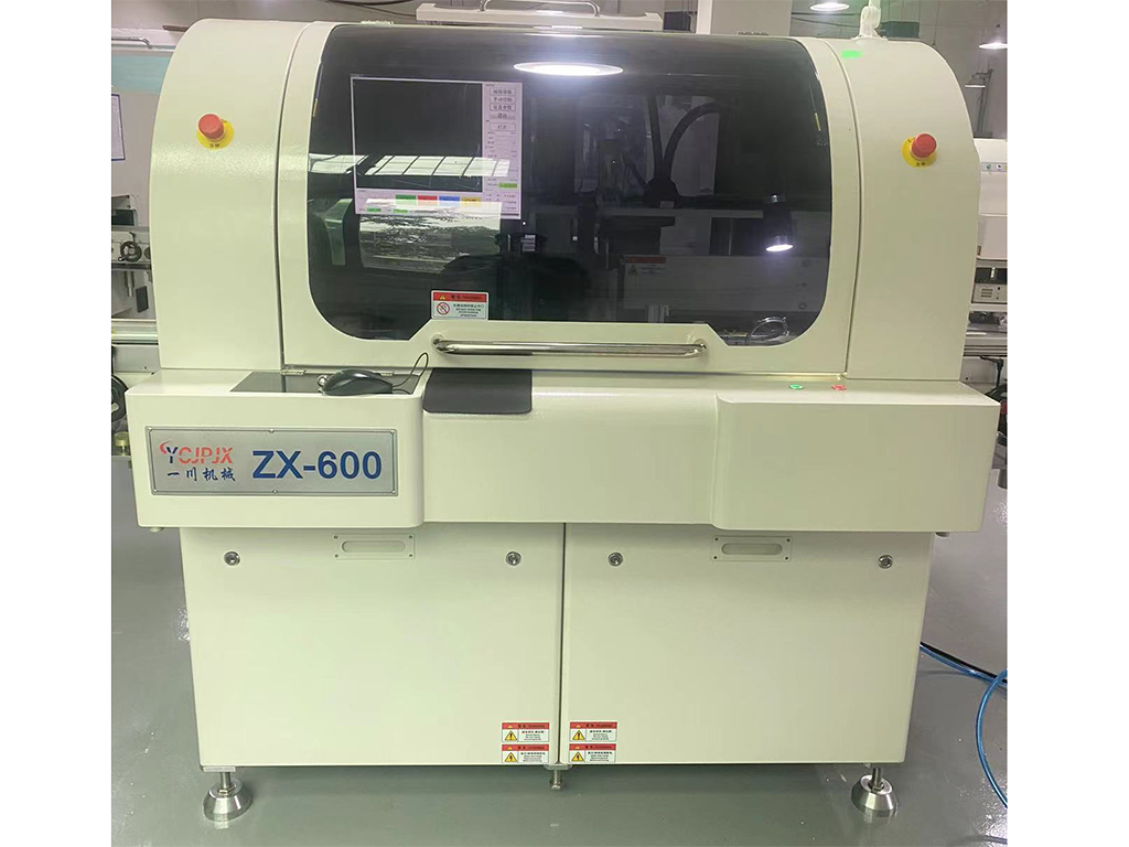
Press fit technology is widely used, and the connection on PCB is one of its typical applications.
When describing in Chinese, we usually use different terms such as crimping, press fitting, and crimping. The industry is often used to directly use "Press fit" to describe. The main focus of this article is also the press fit application in the PCB industry (several common press fit pins).
What are the advantages of Press fit?
The main methods for installing parts on PCB are welding and press fit. Let's compare the advantages and disadvantages of these two connection methods with some conventional data.
| Soldering | Press-fit | |
| consumption | 30-40 kW | 4-6 kW |
| environment | Welding air and residence | No residence |
| cost | Need PA、PPS | No problem of reserved temperature, use lower cost material such as PBT、PET etc. |
| Equipment | Large invest and big area cost | Low invest and small size area |
| Available space | 5-15mm | 2mm |
| Defect rate | 0.05fit | 0.005fit |
From the comparison data, we can see that Press fit is a better PCB connection method than welding in terms of certain performance indicators. Of course, welding is not useless, otherwise there will not be so many welding points on the PCB. For example, welding usually has a greater tolerance for the dimensional tolerance of pins, and the welding connection is more stable, However, Press Fit is better in many feature indicators.
Common Press fit design methods
Before introducing the design method, it is necessary to introduce two commonly used terms:
PTH: Plated through Hole
EON: Eye of the Needle
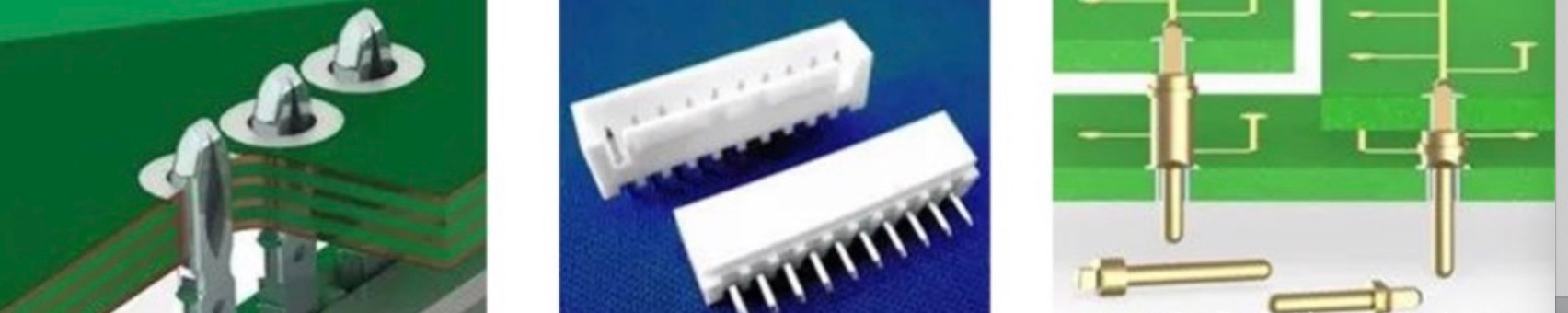
Currently, the pins used on Press fit are basically elastic pins, also known as compliant pins, which are generally larger in diameter than PTH. During the assembly process, the needle parts will be deformed, resulting in the connection surface with the rigid PTH. Compared with the solid needle, the compliant needle can allow a larger PTH tolerance.
The pin hole needle has gradually become the mainstream in the market. It is simple in design and can be used with open patents. Even if it does not require too much design effort, it can also be used with ready-made design solutions, which have the characteristics of low insertion force and high retention force.
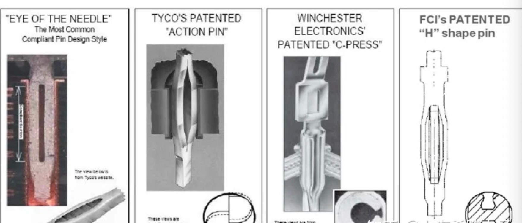
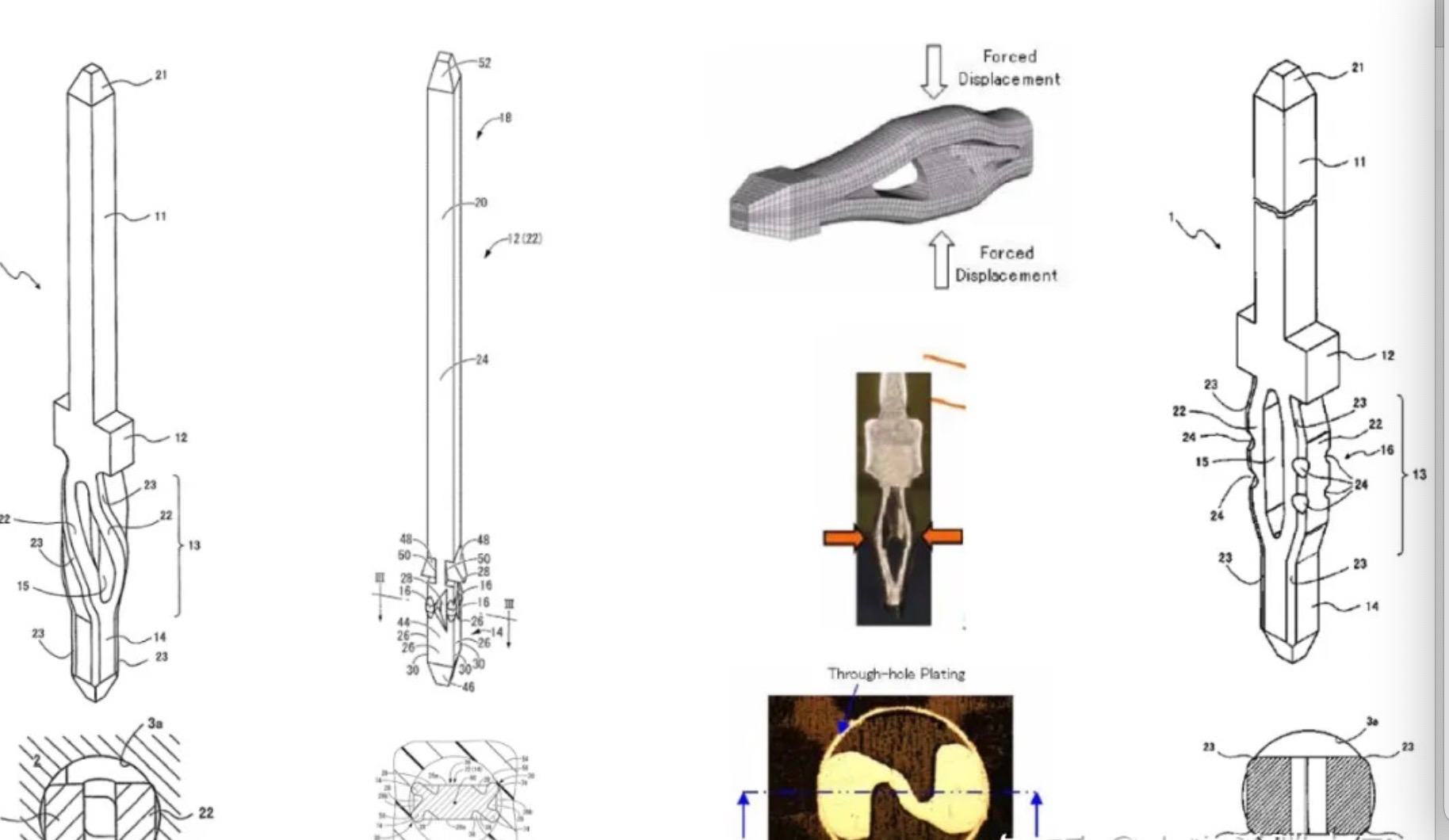
The figure above shows several common pin/terminal structures. The first is the most common design scheme. The basic pinhole design scheme is simple in structure, but requires high symmetry and location; The second is the patent product of TE Company. Based on the pinhole structure, it has a little more rotation angle, which can adapt to different holes. However, it has higher requirements for hole diameter, and it will produce a certain rotation force on the hole; The third is Winchester Electronics' previous patent "C-PRESS", which is characterized by a C-shape from the cross section. The advantages are that the pressing force is continuous, the PTH deformation is small, and the disadvantage is that PTH with small aperture is difficult to achieve; The last one is the H-type contact pin of FCI Company. The advantage is that it is easy to control when crimping, but the disadvantage is that it is difficult to manufacture the contact pin.
Common materials and manufacturing process
Common materials of Pin include tin bronze (CuSn4, CuSn6), brass (CuZn), and white copper (CuNiSi), among which white copper has high conductivity, and the use temperature can exceed 150 ℃; The coating is generally plated by electroplating or hot dip plating μ m+1 μ M of Ni+Sn, SnAg or SnPb, etc. As described above, the structure of Pin is diverse, and the ultimate goal is to produce a Pin with small pressing force and large holding force under the conditions of easy manufacturing and low cost.
The commonly used material of PTH is glass fiber+epoxy resin+copper foil, with thickness>1.6, and the coating is generally tin or OSP. The structure of PTH is relatively simple. Generally speaking, the number of PCB layers is greater than 4. The aperture of PTH is generally strict, and the specific requirements depend on the design of Pin. Generally, the thickness of copper plating is about 30-55 μ m. The thickness of tin deposition is generally>1 μ m。
Analysis of press fit/pull out process
Taking the most common pinhole structure as an example, as shown in the figure below, there is a typical pressure curve change in the whole process of pressing in and pulling out, which is also related to the structural design of Pin.
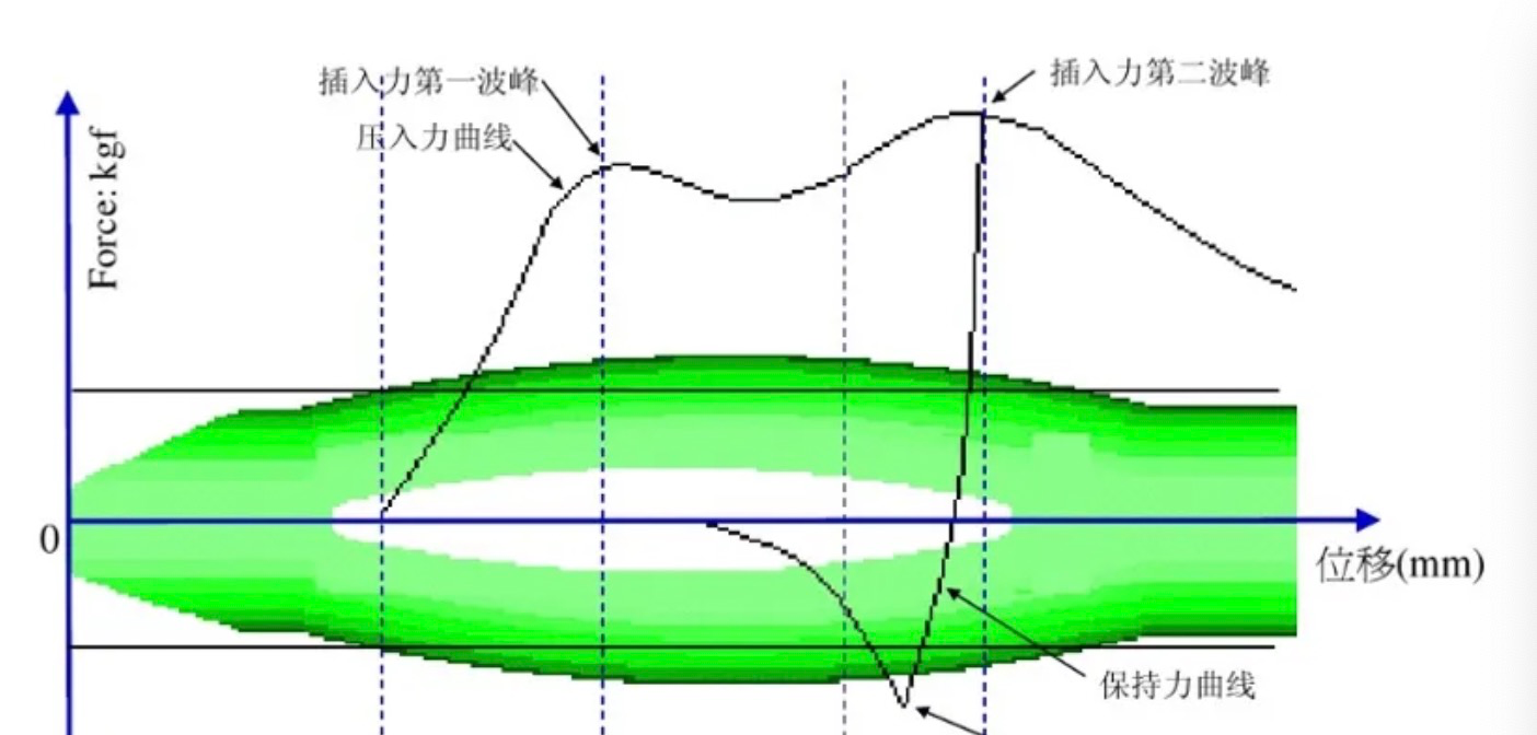
Press in process:
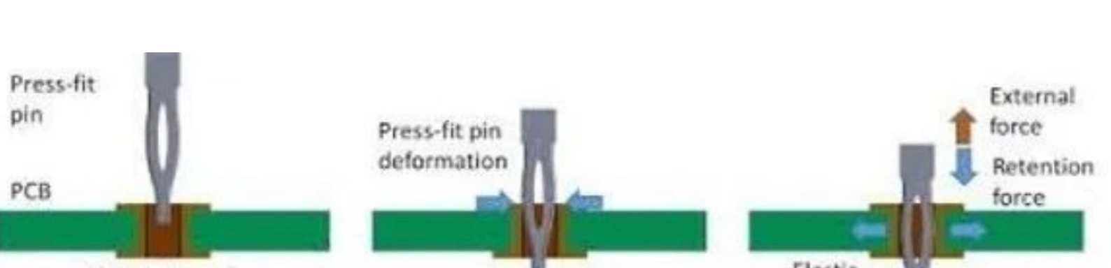
1. Pin is put into the hole, and the tip enters without deformation
2. Pin starts to press in, EON starts to deform, and the first wave peak appears in the pressing process
3. Pin continues to press, EON basically has no further deformation, and the pressing force decreases slightly
4. Pin continues to press down, causing further deformation, and the second wave peak
Appears in the pressing process
Within 100 seconds after the press fitting is completed, the retention force will drop rapidly, with a drop of about 20%. There will be corresponding differences according to different pin designs; 24 hours after the press fitting, the cold welding process of Pin and PTH is basically completed.
This is caused by the physical properties of the metal, and there is little room for improvement. It can be verified whether the final retention force meets the product design requirements through the push out force test.
2. Some failure modes during Pin insertion
As shown in the figure below, the pin may be deformed, crushed, crushed, fractured and bent during insertion
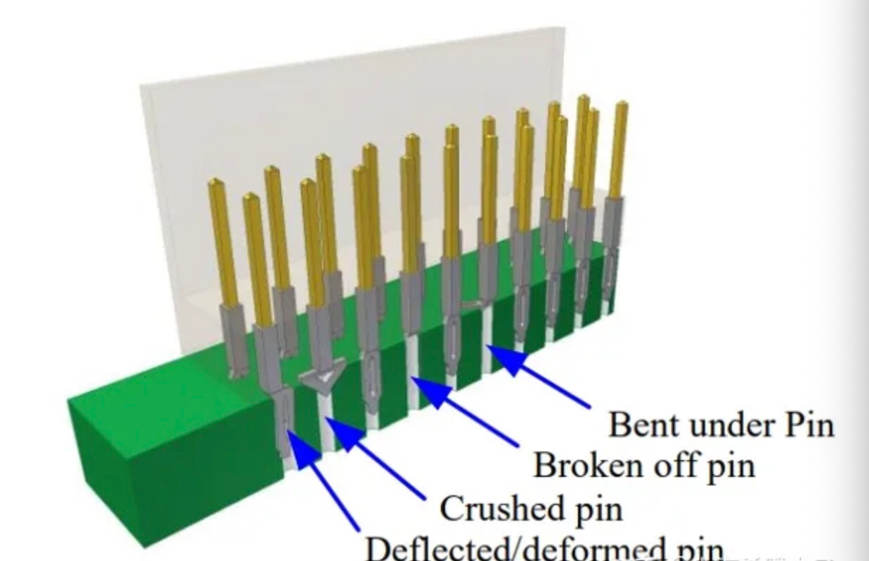
These are the possible failure modes of the contact pin during the press fitting process. Since the contact pin needs to be inserted into the PTH, it is very likely that it cannot be detected visually after pressing, and the damage of the mechanical strength may not be detected through the electrical performance test
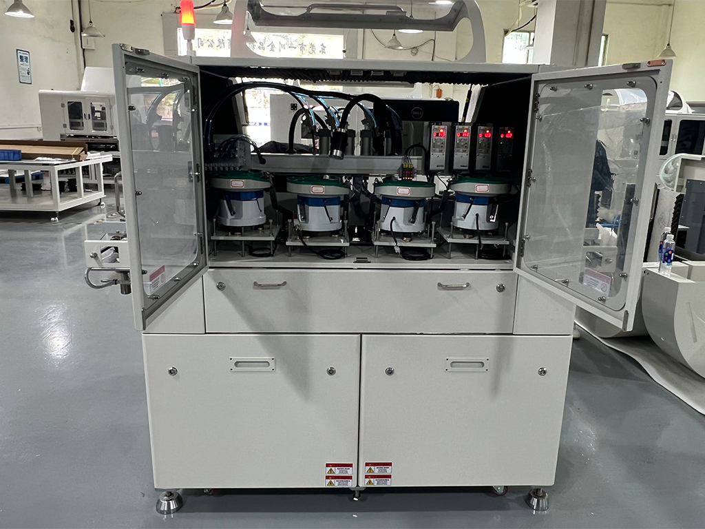
These failure modes need to be monitored during the press fitting process. PROMESS provides curve corridor, window, maximum and minimum value and other monitoring methods to ensure that the whole press fitting process of each pin is controllable and reliable. You can see the case display in the video again. PROMESS provides high-precision, 100% process control solutions to ensure that all products leaving the factory are free of defective products, The process control can also reduce the industrial waste of PCB board to a certain extent and reduce the production cost.
3. Short Circuit
On the surface of pure tin, the stress will promote the growth of tin Whisker, which will lead to the short circuit of the circuit on the printed circuit board, thus endangering the function of the module. The design guidelines for reducing the growth of tin whiskers include reducing the insertion force and reducing the thickness of the tin surface.
Common PTH coating materials include copper, silver, tin, etc
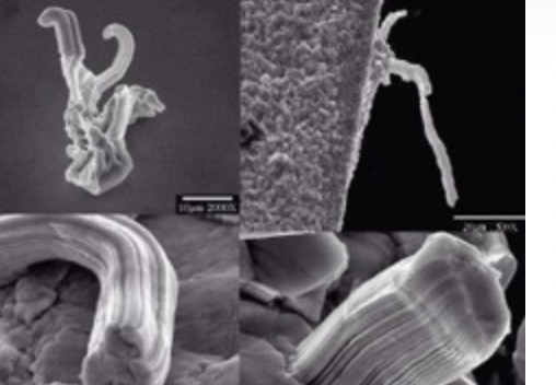
How to solve the problem of tin whiskers?
During pressing, the pressing force shall not be too large, which is the control of pressing process. After pressing, sampling inspection can be carried out, and tin whiskers shall be observed for 12 weeks
4. Open circuit
Jet effect/pull down:
During the process of pressing in Pin, the printed circuit board may be mechanically damaged. If the friction is too large, the surface of the circuit board will be scratched, the friction will increase, and finally the PTH will be pushed out by the phase. Reducing the pressure can also avoid the jet effect.
Whitening effect/delaminate:
During press mounting, each layer structure of the printed circuit board will be squeezed. If the applied force is too large or the PTH is not stable, the printed circuit board may be delaminated. After a period of time, moisture will enter the cracks of the printed circuit board, resulting in reduced isolation performance
These two problems can be controlled to some extent during the press fitting process by controlling the pressing force. After the press fitting is completed, the product can also be inspected by means of contact resistance test and metallographic analysis. The contact resistance test can be used as a routine test item, and the metallographic analysis itself is destructive to the product, so regular sampling inspection can be carried out.
Common product reliability testing methods
One of the common detection methods is aging test and the other is connection characteristic test
Aging is to simulate the state after a long time of use through test equipment. Common aging methods include:
1. Warm flushing: - 40 ℃~60 ℃, continuous change for 30 minutes
2. High temperature: 125 ℃, 250 hours
3. Climate sequence: 16 hours high temperature → 24 hours hot and humid → 2 hours low temperature →
4. Vibration
5. Gas corrosion: 10 days, H2S, SO2
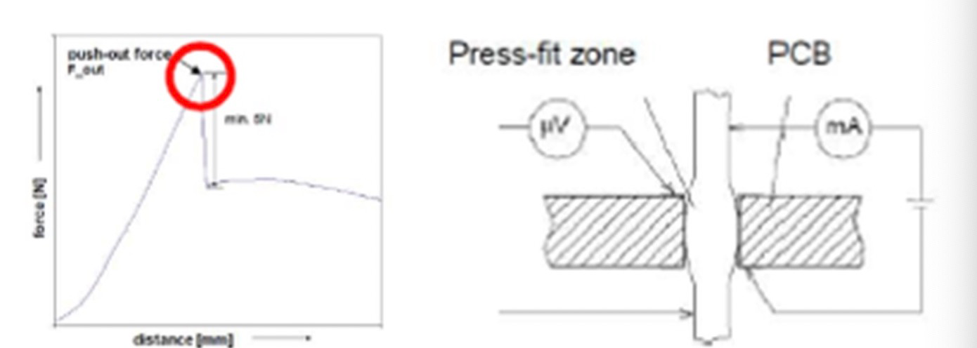
The test is mainly to test the pushing force and electrical performance.
Common methods include:
1. Push out force (holding force): > 20N (according to product design requirements)
2. Contact resistance: < 0.5 Ω (according to product design requirements)
Post time: Nov-10-2022